The questions here mostly revolve around teaching us how logisim works.
Question 1
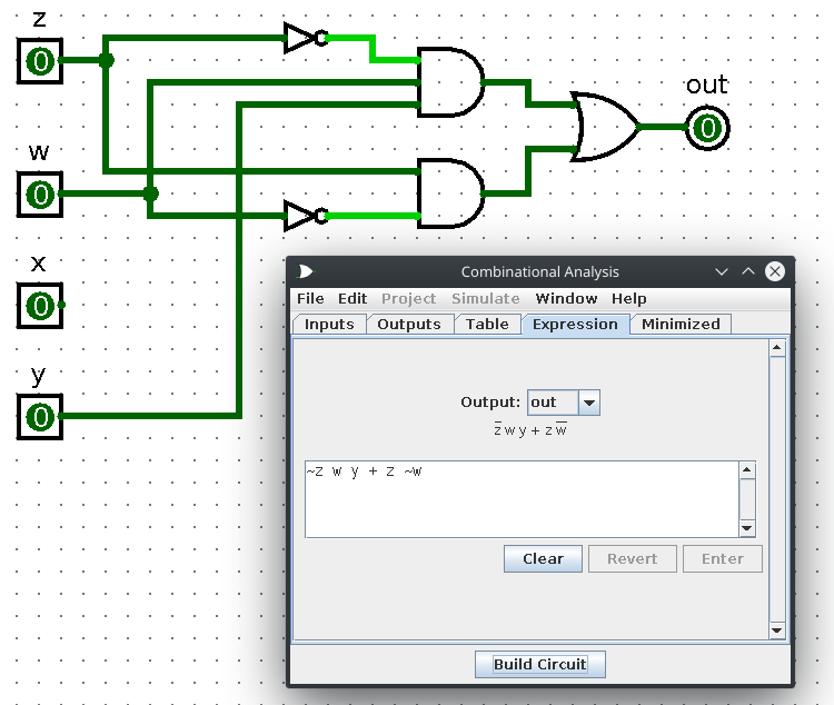
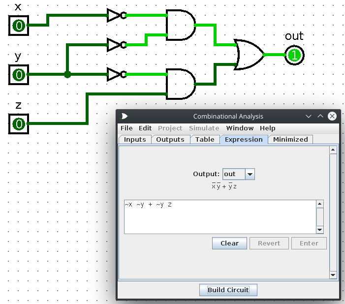
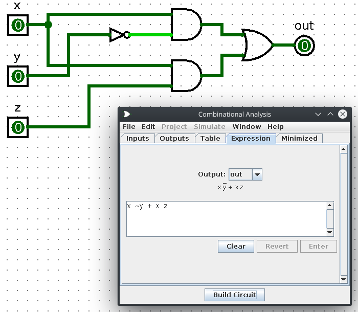
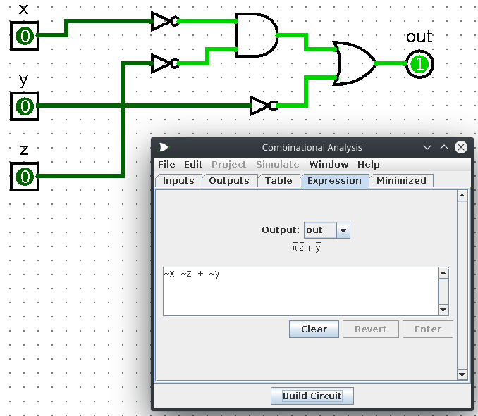
Use Combinational Analysis feature in logisim to build minimized circuits representing the expressions in Exercise 16.
These are rather simple. Go to Window->Combinational Analysis. From there, fill in the inputs (such as for question A, we'd have z, w, x, and y). Make a dummy output (I usually just name mine out or something like that). After that, fill out the expression and build the circuit. From there, you can go to the Minimized tab and click Set As Expression. Now you should have a simplified version of the original expression!
a) z (w + x)1 + w1 x z + w x y z1 + w x1 y z1
b) y1 (x1 z1 + x z) + z (x + y)1
c) x (y z1 + x) (y1 + z)
Question 2
Use logisim to get the answer to Exercise 23.
Pretty simple. Just go to the Table tab under Window->Combinational Analysis and click on the cells to match the given table from the book.
Question 3
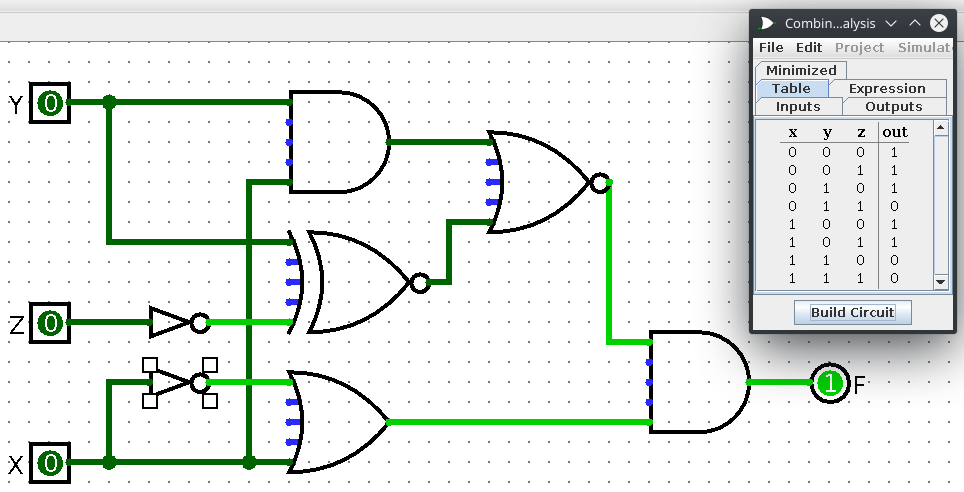
Use logisim to get the answer to Exercise 49.
This one is a little extra. We are given a picture of a circuit and have to construct a truth table based on it. The easiest way to do this is to recreate the circuit in logisim and have it generate the table for us.
Question 4
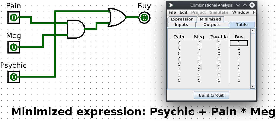
Use logisim to get the answer to Exercise 60. To do this one, I simply wrote what I thought the expression should be based on the description
1) Buy if Pain and Meg both say Yes and the psychic says No
2) Buy if the psychic says Yes
3) Don't buy otherwise
From then, I just did a sum-of-products:
(Pain * Meg * Psychic1) + Psychic
I typed this into logisim and then had it simplify it for me. The result looks like this:
Question 5
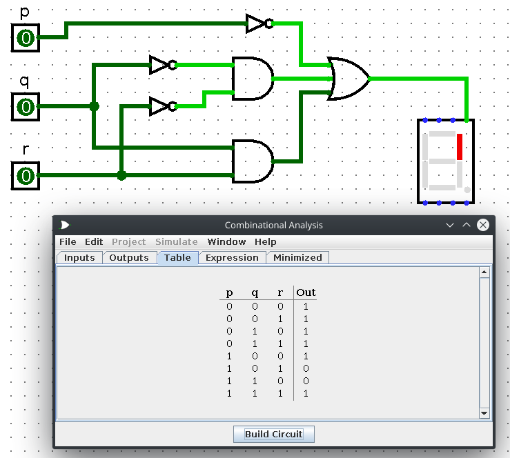
Using the strategy seen in this video, construct the logic circuits required to power the upper right vertical led of a digital display. Do not be alarmed! This is rather simple. So then, in a seven segment display, like what you'd see at baseball games or on older clocks, there are 7 segments that can be lit up to indicate a certain number as seen in the following image:
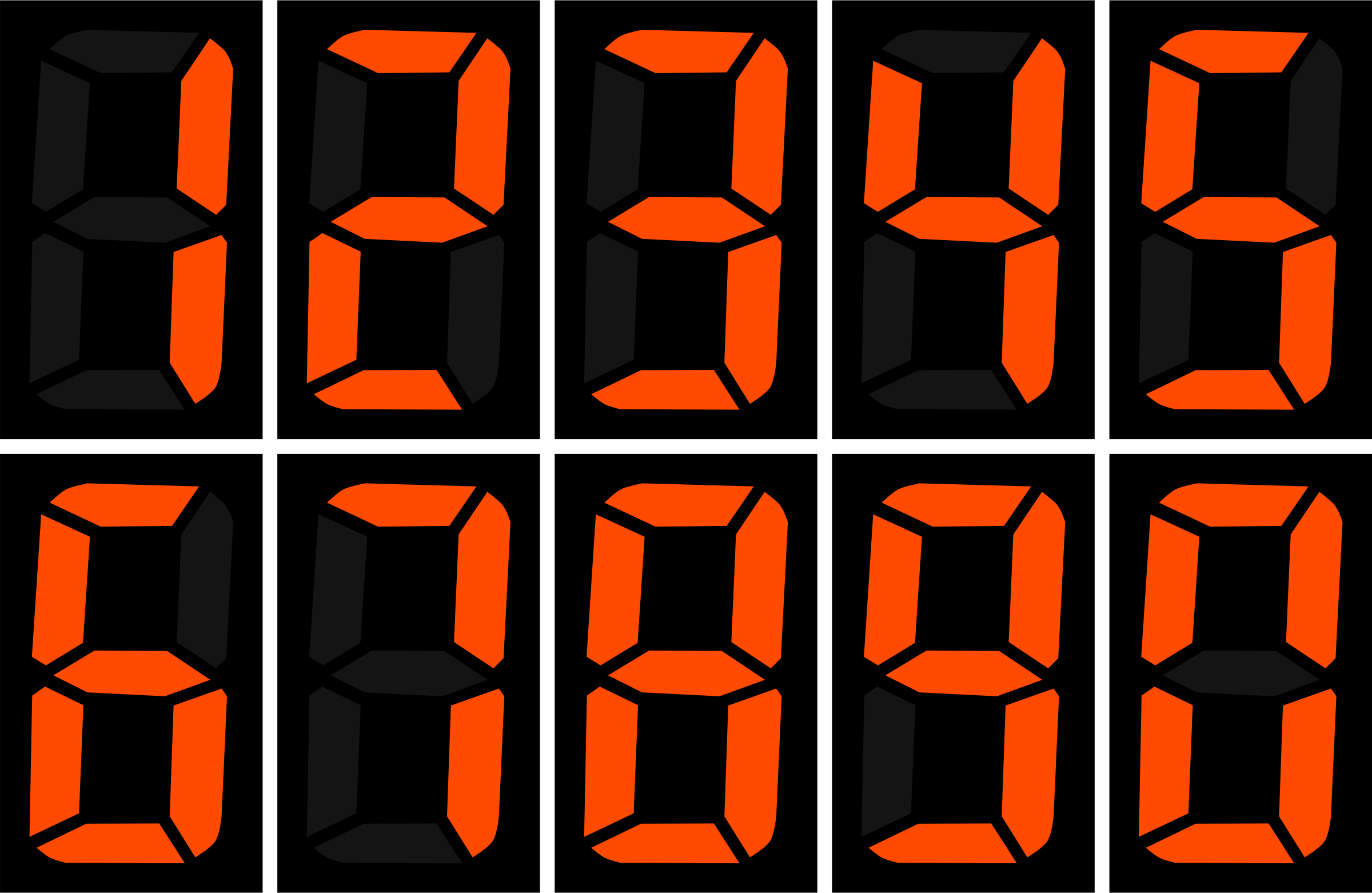
We merely just want the opper right vertical led to light up for the numbers 0 to 7 (in the original homework, he told us to ignore 8 and 9).
The only numbers that should light up in the upper right vertical corner are 0, 1, 2, 3, 4, and 7. Numbers 5 and 6 should not be lit in the upper right vertical corner.
That's great and all but why does this matter? It matters because we represent which number we are currently on via 3-bit binary! 0 is represented by 000, 1 is 001, 2 is 010, etc. Just good old binary counting.
Within the 3-bits, they are referred to as p, q, and r respectively or pqr. p is the leading bit, q is the middle bit, and r is the trailing bit. So in the number 510 we have 1012 with 1 being p, 0 being q, and 1 being r.
WIth this in mind, we can think of the number zero being p1 * q1 * r1 because 010 is just 0002. Five on the other hand is 1012 which can be thought of as p * q1 * r. This same pattern applies to all of the numbers from 0 to 7. This right here is the bread and butter of how we'll go about powering the 7-segment led!
The final expression is thus a sum-of-products of all the pqr combinations!
To make things easy, I simply opened Window->Combinational Analysis in logisim. Under the Inputs tab, I have the circuit take p, q, and r as inputs followed by filling out the Table tab so that only the numbers 0, 1, 2, 3, 4, and 7 output true. Numbers 5 and 6 output false. After that, I simply had it build the circuit and wired it up to the 7-segment led under the Input/Output directory on the left side of the screen!